Dl beginning wire diameter. Sign in to download full-size image Fig 1.

Force And Moment Analysis For Wire Drawing Process In Case Study Factory Download Scientific Diagram
For overall reduction greater than 85 the.
. Reduction is never larger than 100. If there is no work hardening σ Y then the maximum reduction occurs when σ Y ln A 1 A 0 1 A 0 A 1 272 e to 3 sf A 1 A 0 037 63 is therefore the maximum possible reduction of cross-sectional area with a perfect wire-drawing operation for a rigid-plastic material. F_pierce C x t x S where C is the blank circumference t is thickness and S is the shear strength which I normally use as 80 percent of tensile strength.
The material should be sufficiently ductile since it is pulled by the tensile forces. An increase of the wire length. The ideal work derive an expression for the maximum reduction in area per pass for a wire drawing operation for a material with a true-stress strain curve of σKεn Total work Ideal work frictional work redundant work Total work Ideal work 02 x Ideal work 12 x Ideal work Or Total work of deformation 12 u x volume.
Area reduction A 1 -A 2 A 1. The primary emphasis in wire-drawing mechanics is on understanding and defining the relation-ships that exist between these process conditions and the resulting thermo-mechanical response of the wire. The percentage reduction of area r is given by the following equation r 100 x Ao AfAo Where Ao is the initial area and Af is the final area of the wirerod after drawing.
12 SWG -70 Depending on wire material permissible tolerances 8 SWG -50 4 SWG -40 65mm Rod Breaking 30 Maximum When only 30 die in maximum size are needed why procure all dies in biggest pellet. Alternatively the following expression can be used F c st Ao - Af where c is a constant whose value is in the range 15 to 30 depending upon the area reduction lower value for higher reduction and st is tensile strength of material before drawing. The approach angle where the actual reduction in diameter occurs giving the half die angle α The bearing region produces a frictional drag on the wire and also remove surface damage.
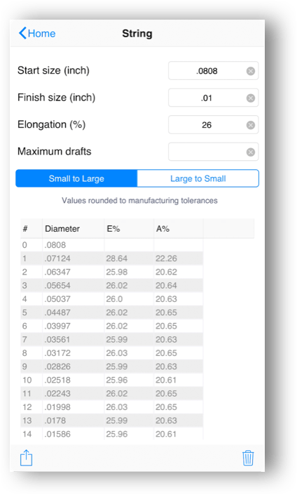
If the size of the incoming wire is known. The formula we use. The incoming wire diameter is calculated from the drawn wire diameter for a given area reduction by using.
For engineering purposes keep the surface area of each drawing station constant. This process repeats until you have reached a number equal to or. Elongation of wire drawing.
The wire is prepared by shrinking the beginning of it by hammering filing rolling or swaging so that it will fit through the die. Approximate expression for drawing force can be written based on plastic work or strain energy. Incoming wire diameter mm inch Øout.
Multiplying the diameter by 71 percent gives 3763 in. As the minimum diameter of the second drawing punch. Slip Roll Speed b Wire Speed d Roll Speed b DIE MATERIAL SELECTION TABLE.
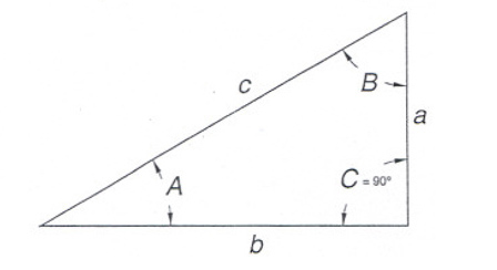
Remember that all dimensions are taken through the centerline of the material. The wire drawing process is quite simple in concept. Usually the wire will require more than one dr.
Reduction in area is not additive r f is not f 1 r 2. Wire drawing die Conical drawing die Shape of the bell causes hydrostatic pressure to increase and promotes the flow of lubricant into the die. The pull force determines the machine capacity needed.
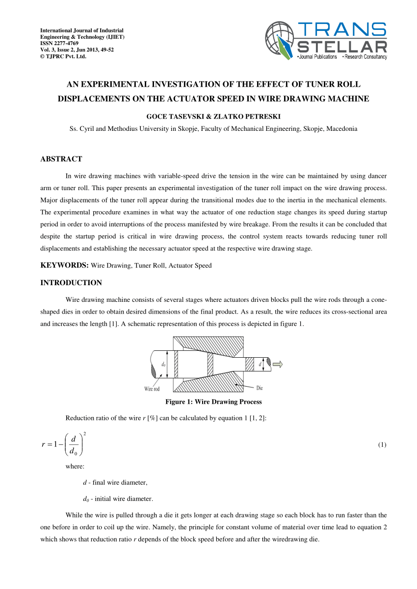
I want to predict when a draw reduction is severe that the bottom of the component will fracture because F_draw is bigger than F_pierce. As the wire is pulled through the die its volume remains the same so as the diameter decreases the length increases. Drawing process Before the actual drawing the material to be drawn is properly prepared.
The drawing of the wire starts with a rod or coil of hot rolled steel which is 08 to 16 mm larger than the final size required. Minimum 00440 01118 Maximum 00396 01005 results in 236 -24 Nominal 00442 01123 Nominal 00394 01000 results in 260 Maximum 00444 01128 Minimum 00392 00995 results in 284 24 2. 10 rows Wire Drawing Formulas.
For ferrous wire step reduction is usually between 7 and 38 limits depend on the product. The chart shows this reduction as 74 percent and 74 percent of 3763 in. View chapter Purchase book Relevant Aspects of Copper and Copper Alloy Metallurgy.
Wire area reduction percentage Inversely the drawn wire diameter is calculated from the incoming wire diameter. In the simplest concept of drawing a break occurs when the draw stress equals the yield andor breaking stress of the wire at the die exit. Both the diameter size and the section of the wire are reduced.
The wire is then pulled through the die. Wire chemistry approach angle lubrication drawing speed and reduction are the most significant. This reduction of section is at the same time balanced by.
Area reduction r is defined as Ao-AfAo -----21 The drawing ratio R is defined as AoAf 11-r -----22 The important parameters which affect the wire drawing force are the drawing ratio die angle material flow stress friction etc. 1241 The ratio of draw stress to flow stress. Wire Drawing Formulas D wire diameter Dl beginning wire diameter Ds ending wire diameter AR reduction in area N number of dies Df finished diameter of the die Bl bearing length A die angle Back A back relief angle D wire diameter Dl beginning wire diameter Ds ending wire diameter AR reduction in area N number of dies.
R n 2. Calculation of lubricant film thickness between wire and die. Schematic diagram of die.
This increase is called Elongation. Many of the technological. In this process there is no force is applied for pushing the wire into the die from the entrance side.
D wire diameter. Reduction is always positive. The total die angle can have values between 5 and 25 and possible percentage reduction in area r of the wire vary between 10 and 50 percent where r 1 A2A1 100.
The requirement of dies to achieve this production at various stages of reduction shall be as under. If this diameter is larger than the product diameter you need a third draw reduction. Drawn wire diameter mm inch A.
During drawing operation each time the wire goes trough a die. Ds ending wire. To find the diameter of the first drawing punch multiply this blank diameter by the percentage given in Figure 1 and subtract the result from the original blank diameter.
Yielding and breaking are generally associated because of the instability created by the plastic stretching of the wire between dies.
Wire Drawing Process Reduction Ratio Of The Wire R Can Be Download Scientific Diagram
Eddie Wire Solutions Software Esteves Group

Algebra Trigonometry And Geometry Formula On The Old Paper Geometry Formulas Trigonometry Old Paper

Mercruiser 5 7 Wiring Diagram Electrical Diagram Trailer Light Wiring Diagram
Wire Drawing Process Reduction Ratio Of The Wire R Can Be Download Scientific Diagram
Formulas By Die Quip
Wire Drawing
Wire And Rod Drawing Ppt Video Online Download
0 comments
Post a Comment